Home / PDV
PDV pulsation damper for screw and rotary vane compressors
Protects oil separator, compressor and pipe network from the sudden pressure relief caused by dryer switching. Install and forget.
How the valve works
If the pressure on the outlet side drops suddenly, the valve piston closes. The compressed air still being delivered by the compressor passes the valve through the bypass bore in the piston. The bore is sized so that a back pressure equal to the operating pressure is held. All parts upstream therefore keep working in quasi-steady-state operation.
Once both sides of the piston have reached the same pressure level again, the valve opens and the flow loss is negligible again. While the valve is closed, the bypass also prevents the compressor-side safety valve from blowing off.
Advantages at a glance
- Eliminates the cause of the problem
- Maintenance-free
- Simple and cost-effective
- Space-saving and cost-effective installation
- Lower component stress through reduced dynamic load
- More environmentally friendly due to reduced oil discharge
- Saves compressed air, which saves energy
The advantages in detail
- Substantially longer life of de-oiling elements through quasi-steady-state operation
- Less stress on compressor components through quasi-steady-state operation
- No contamination of dryer and pipeline network by entrained oil
- No unplanned cleaning costs for the compressed air network
- Compressor maintenance intervals are no longer determined by oil losses and can be planned again
- Drastic reduction in oil consumption (residual oil: see compressor manufacturer's information)
- Simple retrofitting, low retrofitting costs
- No sensitive electrical components, no wiring
- The pulsation damping valve is not a maintenance item: install and forget
- Longer life of the desiccant
- Stable pressure dew point, as the active surface of the desiccant stays oil-free
- No environmental damage from oil discharged with the dryer condensate
- Component cooling (condensation) from expansion of the compressed air is shifted from the compressor to the pulsation damper
- Less emulsification in the compressor
- Saves compressed air and therefore energy (depending on volume and depth of the pressure sink)
Properties
- Simple mode of operation
- Non-corroding materials: housing, valve piston and compression spring in stainless steel
- Compression spring designed for fatigue strength under the dynamic load profile
- No soft seals that could embrittle
- Self-centring valve seat
- Insensitive guidance of the valve piston: it is held and guided by the compression spring alone
- Not a maintenance item
- Any mounting position
Application
Compressed air production
To maintain oil circulation, oil cooling and oil separation, all compressor types with oil-injection cooling need a periphery with oil reservoir, oil cooler and de-oiling filters to de-oil the compressed air.
The weak point
The compressed air is de-oiled by a filter element. Oil separation requires as even a flow as possible through the filter section. Rapid changes in pressure and volume flow lead to undesirable side effects such as drastically increased residual oil content or a severely reduced service life because the filter element is destroyed.
The cause
After compression, the air at the compressor outlet is nearly 100 % saturated with moisture. To avoid corrosion and freezing in the compressed air network, it must be dried downstream of the compressor. In mobile applications (trams, buses …) this is usually done with single- or twin-chamber adsorption dryers, more rarely with membrane dryers.
Adsorption dryers use a constant share of compressed air to regenerate the desiccant. System-induced switching operations (reversal of the chamber functions drying/regenerating and condensate discharge) also need large quantities of compressed air for short periods. The cycle times are pre-set at about 50 seconds to several minutes. With intermittent compressor operation, the pressure line between compressor and dryer outlet is also vented abruptly to atmosphere at every compressor stop, so that the compressor can restart unloaded.
Membrane dryers take air for drying at a continuous rate. Sudden withdrawals are caused here by intermittent compressor operation: at every compressor stop the pressure line up to the outlet of the membrane dryer is vented abruptly.
The physics
The buffer volume between compressor and dryer, usually a short compressed air line, is relatively small. Each cyclic peak in the dryer's demand for compressed air leads to a sudden and drastic drop in pressure. A pressure sink arises and spreads towards the compressor at the speed of sound. The compressed air in the compressor casing expands explosively across the de-oiling filter element to the low level of the pressure sink.
The damage
As a rule, air flows through the de-oiling filter element from inside to outside. With even flow, the smallest oil droplets coalesce into bigger and bigger drops. At the outer surface they collect in the sump of the filter casing by gravity and return to the compressor's oil circulation. Gaseous components remain in the compressed air. Oil separation inherently causes a small, permanent pressure loss.
The pressure sink at the outer surface of the filter raises this pressure differential abruptly. This puts the oil-soaked filter fleece under extreme stress. Initially, the oil on its surface is flung off explosively and carried away with the compressed air, and the residual oil content rises. The alternating pressure differentials wear the fleece down until it tears. Its service life is considerably reduced.
The solution
The pulsmin pulsation damper is used wherever machines or plant components are at risk from discontinuous flow. Pressure disturbances caused by consumers or processes are turned into virtually constant pressure.
Mounting location
- Adsorption dryer: upstream of the dryer, in the pressure line to the dryer or in the compressed air inlet port of the dryer.
- Membrane dryer: downstream of the dryer, in the outlet line or directly at the compressed air outlet, in any case upstream of the relief valve.
Lay the line from the compressor to the valve with a downward slope in the direction of flow so that no condensate collects. Avoid water pockets.
Dimension sheet
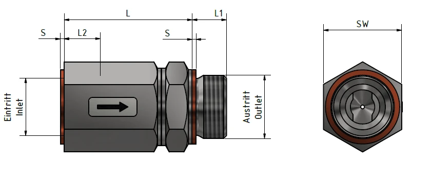
| Volume flow¹ [l/min] | L [mm] | Connection² in/out | L1 [mm] | L2 [mm] | S [mm] | SW (AF) [mm] | Weight [kg] |
|---|---|---|---|---|---|---|---|
| 100 – 800 | 53 | M 22×1.5 | 14 | 14 | 1.5 | 32 | 0.27 |
| 100 – 800 | 53 | G ½" | 14 | 14 | 1.5 | 32 | 0.27 |
| > 800 – 3,000 | 67 | G 1" | 18 | 18 | 2 | 41 | 0.5 |
| > 3,000 – 4,000 | 70 | G 1¼" | 20 | 20 | 2 | 46 | 0.85 |
¹ Volume flow at 20 °C, 1 bar, air. ² G (inch) threads to DIN ISO 228-1; M 22×1.5 is a metric fine thread. Housing, piston and compression springs in stainless steel. Subject to change, as of 1 December 2024.