Home / PDV-DS
PDV-DS pulsation damper with damper disc for piston compressors
Damps the discharge pulsation of reciprocating compressors and protects against the pressure sinks of dryer switching at the same time.
Tasks
- Damping the discharge pulsation of reciprocating compressors, to avoid harmful effects such as the disintegration of the desiccant granules into dust.
- Reducing the harmful effects of sudden pressure drops, such as dynamic component stress.
Solution
Damping the discharge pulsation
The effect of the standard pulsation damping valve (PDV) is largely based on the deflection (3 × 90°) of the delivered air at the valve piston. Part of the pulsation energy is converted into heat by friction in the deflections (dissipative damping). A damper disc (DS), installed upstream of the valve piston in the direction of flow, reduces the discharge pressure pulsation.
The damper disc works by reflection and dissipation. It acts as a reflection point within the pipeline: the propagation of the pressure pulsation into the downstream system is prevented by reflecting the pulsation energy, and “standing waves” in the pipeline are destroyed at the same time. Due to the increased flow friction in its bores, the disc also has a dissipative effect: as air flows through the bores, pulsation energy is converted into heat by the friction of the molecules, further reducing the pulsation.
Protection against the pressure sink
Besides reducing the pulsation, the combination of PDV and DS protects the upstream system against sudden pressure drops, for example from the system-induced switching of an adsorption dryer. The upstream system keeps working in quasi-steady-state operation. Sudden pressure sinks mean increased component stress through dynamic load; with pulsation dampers, the service life (permissible load cycles) of thin-walled components such as coolers and filters has been increased significantly.
Thanks to the wear resistance of its materials and their resistance to aggressive media, the PDV with DS is maintenance-free.¹ Periodic inspection or maintenance, as for a pressure vessel, is not required.
¹ Requirement for the medium: purity (solid impurities), degree of filtration 99.9 % (5 µm).
Risk assessment
Frost and freezing
Permissible mounting position vertical or horizontal. Lay the downstream line with a slope towards the condensate outlet so that no water collects; water pockets should generally be avoided. In operation as well as when depressurised, the valve is held open by the spring force, so any condensate can drain along the slope. Should the valve piston freeze to the damper disc on the inlet side, the warm compressed air can still flow through and thaw the valve. With horizontal mounting and water collected under the piston, a sufficient residual cross-section always remains free for the compressed air.
Corrosion
All components are made of stainless steel (1.4301).
Compression spring
Designed for fatigue strength.
Experience
pulsmin pulsation dampers have been on the market since 2001. Among other applications, they are installed in compressed air systems for Russia that have been verified down to −50 °C.
Damping and pressure loss of a PDV-DS G 1" were measured on an oil-free, two-stage piston compressor in a shunting locomotive (2,150 l/min intake volume flow as stated by the compressor manufacturer, 10 bar gauge upstream of the valve): the discharge pulsation was reduced by 40.3 % at a pressure loss of 155 mbar. Adapting the valve further to the delivery flow increases the damping at the cost of a higher pressure loss, for example to about 60 % at around 280 mbar. The measurement report by Kötter Consulting Engineers is available under Documents (German).
Mounting location
- Adsorption dryer: upstream of the dryer, in the pressure line to the dryer or in the compressed air inlet port of the dryer.
- Membrane dryer: downstream of the dryer, in the outlet line or directly at the compressed air outlet, in any case upstream of the relief valve.
Dimension sheet
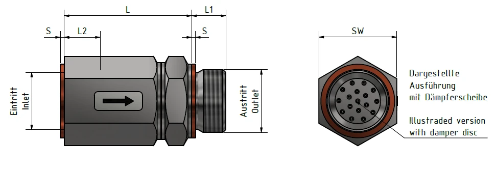
| Volume flow¹ [l/min] | L [mm] | Connection² in/out | L1 [mm] | L2 [mm] | S [mm] | SW (AF) [mm] | Weight [kg] |
|---|---|---|---|---|---|---|---|
| 100 – 800 | 53 | M 22×1.5 | 14 | 14 | 1.5 | 32 | 0.3 |
| 100 – 800 | 53 | G ½" | 14 | 14 | 1.5 | 32 | 0.3 |
| > 800 – 3,000 | 67 | G 1" | 18 | 18 | 2 | 41 | 0.56 |
| > 3,000 – 4,000 | 70 | G 1¼" | 20 | 20 | 2 | 46 | 0.93 |
¹ Volume flow at 20 °C, 1 bar, air. ² G (inch) threads to DIN ISO 228-1; M 22×1.5 is a metric fine thread. Housing, piston and compression springs in stainless steel. Subject to change, as of 1 December 2024.